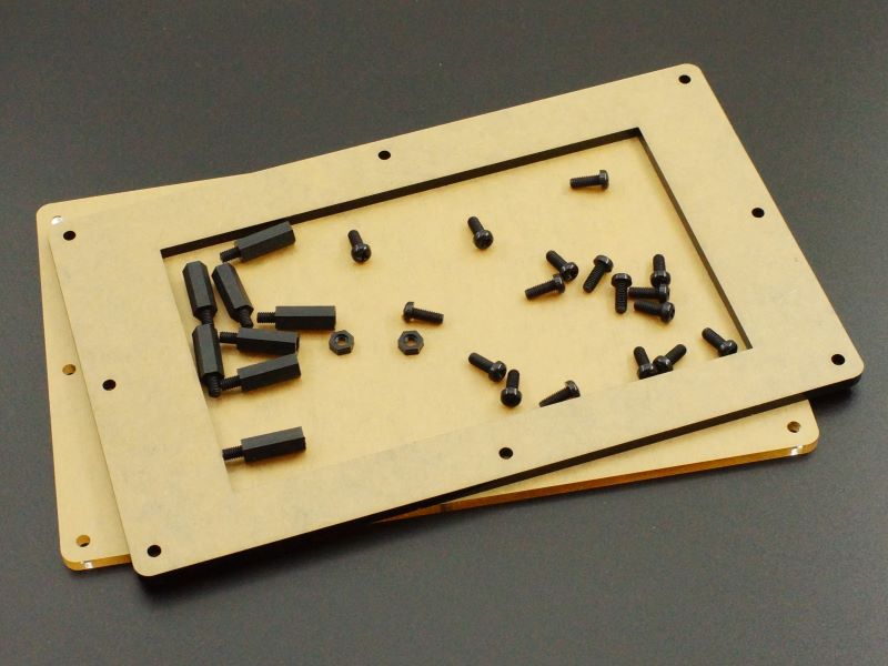
Description This acrylic enclosure kit provides a basic 2-panel open-sided enclosure for the Project System for Teensy 4.1. PACKAGE INCLUDES: Front Panel, Black Acrylic, 4.5mm Back Panel, Clear Acrylic, 4.5mm Qty 8 – M4 x 18mm M/F Black Nylon Standoffs Qty 17 – M4 x 10mm Black Nylon Screws Qty 4 – M4 Black Nylon Nuts This kit also reuses some of the hardward that comes with the Project System baseboard to complete the assembly. ASSEMBLING THE ENCLOSURE Installing the M4 Standoffs: The Project System for Teensy 4.1 ships with qty 9 M4 x 20 standoffs that serve as feet when working with the baseboard. When assembling the baseboard into the acrylic enclosure, first remove those installed standoffs and move them to the Teensy side of the baseboard. Instead of reinstalling the screws to hold the standoffs in place, the M4 x 18mm M/F standoffs supplied with the acrylic panels are screwed into those standoffs from the LCD side of the baseboard as shown below. The center standoff under the LCD is still secured with one of the screws or can just be left off if desired. Note Possible Standoff interferences: If an Audio Adapter or other adapter is installed in the first adapter slot or a large adapter is installed, the adapter board interferes with the standoff in that location. In this case the standoff can be left off and one of the supplied nuts can be used to hold the front panel standoff in place as shown below. Alternatively, in the case of the Audio Adapter, it can be moved to the 2nd slot to the right where there is no mechanical interference. This moves the Audio Adapter farther from the Teensy which is not as ideal from a signal integrity perspective, but in our testing, this configuration has not shown to create any issues. A similar interference can occur with the 40-pin I/O expansion connector. Right-angle male connectors fit OK with standoffs on either side, but if a straight male connector is installed, there is not enough clearance to fit the female IDC cable connector on the side near the MIDI connectors. In this case, the standoff can be left off in this location and the front panel standoff secured with a supplied nut as shown below. Install the LCD if not already installed: The LCD is installed using the 4 M3 x 11 nylon standoffs with 8 stainless steel M3 screws. If the LCD was on the extender cable with the longer 22mm standoffs installed, be sure to swap them out for the shorter 11mm version. The 4 screws attaching the standoffs to the baseboard PCB have M3 nylon washers added to guard against any possible shorting hazard. When installing the screws on the LCD side, the screw heads are close to the LCD glass, so use some care not to chip the glass with the screwdriver. Installing Front Panel: Note that the LCD opening is not quite centered left to right or top to bottom in the black acrylic front panel. The two narrower acrylic sides go toward the corner by the Ethernet connector. If in doubt, rotate / flip the acrylic piece until the screw holes line up and the LCD opening covers the edges of the LCD so that only black shows through the opening The protective paper should be removed from both sides of the acrylic before securing with the 8 M4 x 10mm screws. When attaching the panels, it is best to get all the screws started before tightening them all down. Note that the baseboard may have shipped with 8mm long screws in the standoffs. Longer 10mm screws are supplied with the acrylic kit to give more threads for attaching the thicker acrylic panels, though the 8mm will still work OK in a pinch. Installing Back Panel: The back panel just needs to be rotated/flipped so that the slot for accessing the screw terminals is positioned over the CAN bus and RS485 screw terminals. After the protective paper is removed, it is secured with 9 M4 x 10mm screws. Obviously if some of the standoffs were not installed, you will need to use fewer screws. Standoff Options: The 20mm standoffs that come with the baseboard are just long enough to clear the MIDI connectors and give the thinnest profile. Longer 30mm and 40mm standoffs are available to be ordered separately at the bottom of the page if it is desired to raise the height of the bottom acrylic for clearing higher components that may be installed or if a thicker assembly is desired for sitting the assembly on edge. Notes: None Technical Specifications Dimensions L x W Acrylic Panels 224.73 x 138.33mm (8.85 x 5.45″) L x W x H (enclosure assembled) 224.73 x 138.33 x 48mm (8.85 x 5.45 x 1.9″) Material Front Panel 4.5mm Black Acrylic Back Panel 4.5mm Clear Acrylic Standoffs and screws M4 Black Nylon